You can create 2D drawings from your 3D model by exporting views. For each view export, you can use all objects or only selected objects. Exported objects can be clipped to a defined rectangle, if you need to create only a small detail from a larger part.
Once 3D views are exported into 2D area, corresponding dimensions, axes or hatches are updatable. After changes in 3D and switching mode to 2D, they are adjusted automatically. See Automatic Updates of Dimensions, Axes and Hatches after Changes in 3D
2D View from 3D - 32E |
The following options are available for exporting views:
Define the export method, and select the exported objects, if necessary. Define the view position in the 2D drawing. Optionally, you can define 2D position using drag and drop or by translation new objects. If the latter possibility is used, define a translation vector (position “from”, position “to”) and confirm the insertion. 3D section outlines are exported to 2D as boundaries that can be detected as a single object. This boundary can be easily used in hatching functions. See Hatching 2D Objects.
You can also set a position of each view in 2D area:
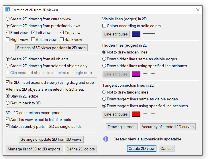
3D View export definition
The view export is added to a list of predefined exports, if during the export creation the option “Add this view export to list of exports” is selected.
The view export list is used whenever you need to update 3D views after 3D changes. Each stored view export contains:
If the view update function is invoked, each export from list is performed. For each export the view is set, the corresponding section is turned on, objects are selected and the 3D view is exported to 2D. These objects are inserted into 2D. All this is done automatically. You can select whether the old 2D objects will be removed or changed, to distinguish line attributes before and after the update.
If you choose to change line attributes of old 2D objects, you can switch between old 2D objects and new 2D objects. This switching always highlights changes, and you can see what is new or what was deleted. Exporting a view creates only outlines. If there are any dimensions, hatches, or other 2D annotations, you can adjust them according to the changes. When all additional 2D changes are complete, remove the previous view export. If this view is not removed, the 2D update cannot be performed.
3D section outlines are exported to 2D as boundaries that can be detected as one object. This boundary can be used in hatching functions. See Hatching 3D Sections.
Update 2D after 3D Changes - 32EN |
Creates new 3D-to-2D view exports. If reexports are already defined (if 2D views are already created, reexports are defined by default), you can update 2D from pop-up menu. Click an empty area to obtain menu containing general options. Or, 2D is updated if you switch into 2D mode and select update from pop-up menu.
Management of method of 2D drawing updates and management of individual 3D views exported into 2D is available from dialog panel Exporting Views and Sections from 3D to 2D - see description of command above.
Old/New View Export, Updated 2D - SON |
In 2D, switch between old and new 3D to 2D view exports to compare and update 2D after 3D changes. This allows you to easily distinguish changes and modify the corresponding 2D objects – especially dimensions and hatching.
Remove Previous View Export - ROL |
In 2D, remove all old 2D view objects exported before the last export. Perform the function after all changes in 2D are finished.
We do not recommend to keep old and new exports, if dimensions are automatically updated.
Methods available for checking of automatically updated dimensions are described here.
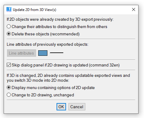
Updating 2D after changes in 3D. We recommend to set skipping of this dialog for each switch into 2D mode.
Update 2D after 3D Changes Setting – 32SET |
Manages a list of predefined view exports. This function is available also from Update 2D after 3D Changes or from Creating 2D from 3D. The view export can be selected from the list as well as from corresponding 2D objects. You can:
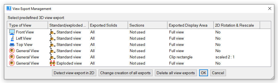
Management of defined view exports
There are differences between export definitions from standard view and from exploded view. For more information, see Exploded Views of Assemblies
With VariCAD you can create 3D sections. Sections can be turned on or off at any time. If a section is active, displayed solids are cut by the sectioning tool. If the solid is part of an active section, some functions cannot be performed. If this happens, you will receive a warning message.
Each section is defined by:
If you need to change the color of the section planes, use function Change Color. Switch the select mode to selection of single solids (single parts of Boolean trees) and select a section plane as an object for color change.
For more information about exporting sections to STEP or IGES, see How 3D Objects Are Converted to STEP or IGES.
Section planes are the planes of the sectioning tool. If the section is turned on, operation similar to Boolean cut is performed and the sectioning tool cuts the sectioned solids. As a sectioning tool, you can select a box or any solid created by extrusion. If the extruded profile contains more lines, the section has more section planes. Shape or location of sectioning tool defines how the solids are cut by sectioning.
Instead of insertion of a single solid (box or extruded solid), you can select a section plane directly – using similar method as in Cut by an Extruded Solid. Then, create a section tool contour and select its height and location.
Such section tool is edited by sketching and redefinition of extrusion height.
We recommend to create section tools with certain excess to all directions. If you enlarge sectioned solid by shape editing, section may be compromised – the section plane is not intact. In such case, select editing of section tool and enlarge it too.
3D Section Management - SEM |
Turns on or turns off selected section. Allows you to define a new section, define the sectioned solids, section planes or cancel definition of 3D section.
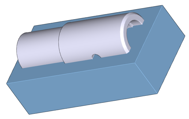
3D section - the box is the sectioning tool
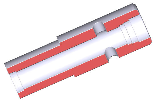
Sectioning result, the view is rotated
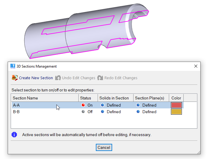
3D sections management. If a line in the table is highlighted under cursor, corresponding section contours are highlighted in 3D.

|
|

|